Bridge span welding simulation – Europe – West China route
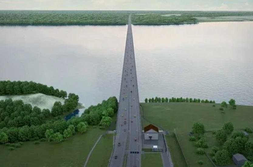
Nova-Engineering specialists have completed a project on computer simulation of control samples welding of the all-welded span structure of the bridge over the Volga River near Tolyatti. A detailed description of the design, drawings, and description of the assembly/welding sequence of the all-welded joint of the control samples is reflected in the article, which can be soon downloaded from the link (now a detailed version of the article is published in several industry publications).
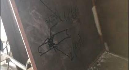
A video from the field is on the right. When having a tight deadline, our specialists were forced to agree on the spot and sketch an approximate welding technology that needed to be calculated right at the bridge assembly site.
Welding strain inevitably occurs in the process of welding bridge spans. One of the critical reasons for the occurrence of strains during welding using filler material is the physical effect known as thermal expansion of bodies. Most metals and alloys expand with increasing temperature and contract with decreasing temperature. When welding with additive material, molten material falls on the heated edges of the parts to be welded, which, when cooled, begins to shrink and tighten the welded joint area. A plastic strain occurs.
This effect is the basis of the method of fictitious forces – a computational method that allows simulating strains during welding. Using the linear expansion temperature ratio (LETR) and the temperature difference between the ambient temperature (assumed to be 20 °C) and the melting point of the material, relative strains are obtained that are applied to a particular area of the welded joint.
The method of fictitious forces is approximate. When using it, the actual heating and cooling cycle of the material is not taken into account. LETR constancy is also the assumption – it is assumed that it does not depend on temperature. Simultaneously, the described method allows for fairly fast calculations, but it is not very accurate and requires calibration. The size of the area to which the fictitious forces will be applied is not known in advance and can vary significantly for different types of joints, material thicknesses, etc. A more accurate and more resource-intensive calculation method is used to calibrate the method of fictitious forces – the moving heat source method (MHS).
The simulation showed and predicted a well-known type of welding strain – "welding house." The numerical values of the welding strain are also quite realistic and have been observed in practice.
The first stage of the work immediately showed that numerical calculations could obtain various types of welding strain.
During the welding process, the loose control sample begins to move along the horizontal X-axis. The most significant displacements occur in the upper belt area. At the same time, it rises from its original position – the free edge of the sample is shifted in the positive direction of the Z-axis.
According to the work results, the places of the most likely occurrence of warping and their magnitude were identified. The virtual experiment was the basis for the welding process. The performed physical and mathematical studies have shown that welding processes at the present stage of development of computer technology and software algorithms are amenable to mathematical modeling. The article deals in detail with insufficiently accurate experimental determination of the values of welding strain during traditional work.
Performing field studies on control samples made for the bridge over the Volga River near the city of Tolyatti is irrational to carry out for each studied object. Simultaneously, the calculations performed showed that in terms of the required welding strains, the mathematical method error is 10% compared to the full-scale experiment, which can be characterized as a very high accuracy for this type of calculations and studies. It is proposed to develop this experience and use mathematical analysis more effectively to clarify the parameters of understating the welded blocks, which allow assembling all-welded superstructures with fewer deviations from the design geometry.
We are happy that our expertise helps implement such large-scale international projects, and new technologies improve our country's infrastructure! The calculations were performed in the ESI SYSWELD software package.
Pictures attached on the right side of the page:
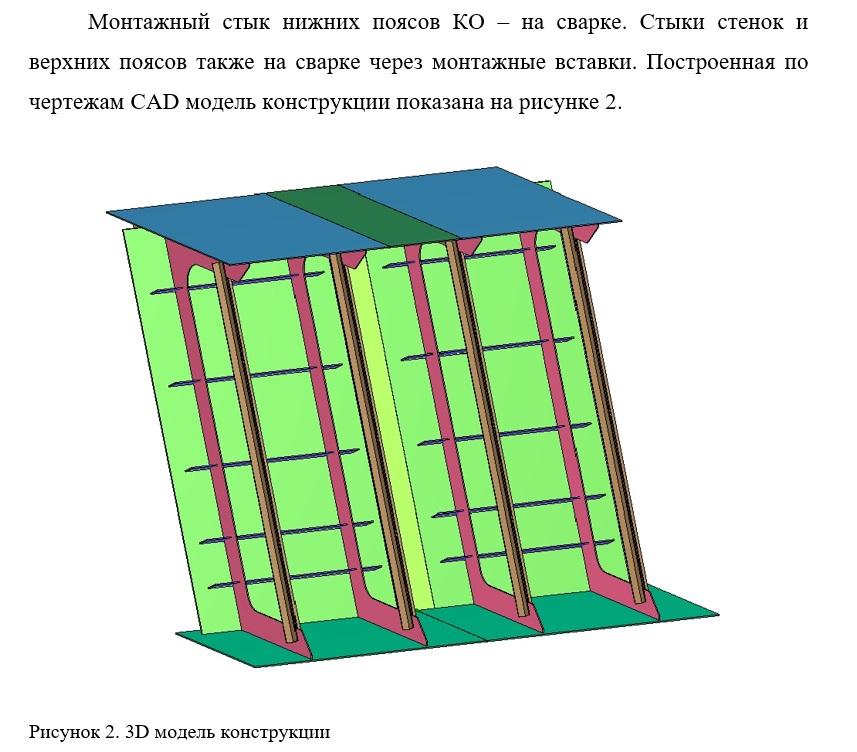
- Pic. 1 – Mounting joint of the lower belts – welding. The joints of the walls and upper belts are also welded through mounting inserts. The construction model according to CAD drawings is shown in Figure 2.
- Pic. 2. – 3D model of the structure
- Pic. 2 – Figure 6. Shell model construction scheme
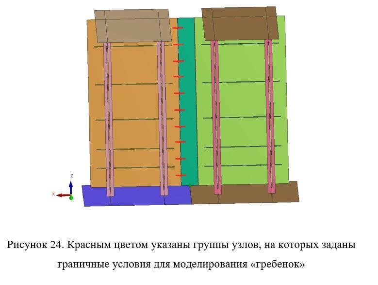
- Pic. 3 – Figure 24. The red color indicates the groups of nodes on which the boundary conditions for the "comb" simulation are set
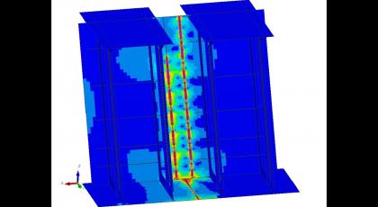
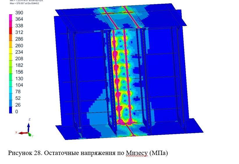
- Pic. 4 – Figure 28. Residual Mises stresses (MPa)
- Pic. 5 – Figure 18. Connection N1. Z-axis deformations, x5 magnification